Applications - SciCore Instruments
Main menu
Applications
Hardware Configuration
Besides outputting the two waveforms from the SMA connectors, the AWG2300 provides other functional signals include analog input, analog output and digital IO lines accessible to the user on the screw type terminal blocks installed on an optional signal expansion board (AWG2300-
To connect a signal wire to a screw terminal, prepare the wire by stringing ~5mm of insulation, insert the wire into the screw terminal, and securely tighten the screws with a flathead screwdriver.
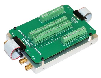
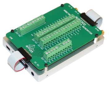
FIGURE (UP) Front view
FIGURE (UP) Back view
Application Software Development
It is not difficult for the user to write customized application software to communicate with the instrument. After successful installation of the software driver, the AWG2300 is appeared as a virtual COM port on the PC. Traditional RS232 style text commands are used for communication between the instrument and PC. For the complete list of the command set that is supported by the instrument please check the AWG2300 user guide.
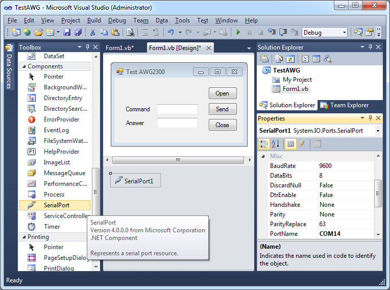
Figure (UP) For example in the Microsoft Visual Studio development environment, by adding a "SerialPort" component to the project the developer can implement communication and control functions of the instrument immediately.
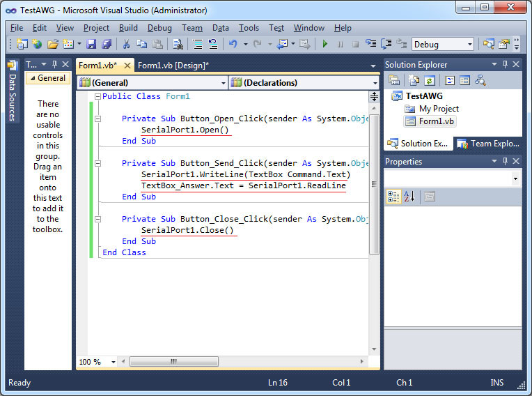
FIGURE (UP) Adding four lines of code to open and close the communication with the instrument, and send and receive messages from the serial port that is associated with the AWG2300.
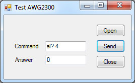
FIGURE (UP) Test to run the program and send a simple command "ai? 4" to read the voltage input to AI 4. The received answer of "0" means a 0V voltage has been read to the program. For the complete list of the command set that is supported by AWG2300 please check the user guide.